


| Specification | LRS-400-12 | LRS-400-15 | LRS-400-24 | LRS-400-48 |
| DC output voltage,current | 12V 0~33A | 15V0~26.6A | 24V0~16.5A | 48V 0~8.3A |
| Wave and noise | 150mVp-P | 150mVp-P | 150mVp-P | 200mVp-P |
| Inlet wire stability | ±0.5% | ±0.5% | ±0.5% | ±0.5% |
| Load stability | ±0.5% | ±0.5% | ±0.5% | ±0.5% |
| Efficiency | 85% | 86% | 88% | 89% |
| Adjustable range for DC voltage | ±10% | ±10% | ±10% | ±10% |
| Input voltage range | 90–132VAC / 180–264VAC by switch; 240–370VDC; 47–63Hz | |||
| Impact current | Cold start current 60A/230VAC | |||
| Overload protection | 110%~150%cut off the output,automatic recovery | |||
| Over voltage protection | Hiccup mode with automatic recovery after the fault condition is removed. Confirm the approved overvoltage threshold for the ordered version. | |||
| Setup,rise,hold uptime | 1500ms,50ms/230VAC 1500ms,50ms/115VAC | |||
| Withstand voltage | I/P-O/P:1.5kV I/P-FG:1.5kV O/P-FG:0.5kV 1minute | |||
| Isolation resistance | I/P-O/P I/P-FG O/P-FG:100M Ohms/500VDC/25℃ /70%RH | |||
| Working temperature | -20℃~+70℃ | |||
| Dimension | 215×115×30mm | |||
| Weight | 0.76kg | |||
| Packing | 37.5×25×26CM/20PCS/16kg | |||

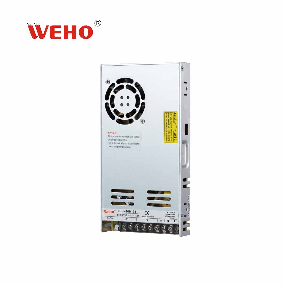
LRS series 400w AC to DC single output switching power supply
The LRS-400 is a 400W-class single-output enclosed power supply with a 30mm-high body. Select 90–132VAC or 180–264VAC using the input-range switch; the DC input range is 240–370VDC and the AC frequency range is 47–63Hz. Output versions are 12V, 15V, 24V and 48V. Match the exact model suffix and listed current range to the load.
LRS-400 series serves as a high-price-to-performance power supply solution for various industrial applications. The enclosure is fan-equipped; keep ventilation openings clear.
If you have any questions, please do not hesitate to contact us at Email: [email protected]
Email Us [email protected]
- Description
Mechanical dimensions
| Body length | 215 mm |
|---|---|
| Body width | 115 mm |
| Body height | 30 mm |
| Width including mounting ears | 135 mm |
The body dimensions and mounting-hole dimensions are different references. The vector drawing below retains the dimensions printed in the WEHO original.
On a small screen, swipe the drawing horizontally to inspect every dimension. No separate drawing image or script download is required.
Overview
The LRS-400 brings four documented single-output choices to a 215 × 115 × 30 mm package: 12 V, 15 V, 24 V or 48 V. It can be considered for local electronics around textile inspection, materials identification and print-registration equipment when the selected DC input and load budget are compatible. The 24 V model is listed at 0–16.5 A, while the 12 V, 15 V and 48 V models have their own current entries. Input is 90–132 VAC or 180–264 VAC by switch, with 240–370 VDC separately specified. Plan branch demand, thermal conditions and fault recovery around the chosen suffix rather than treating the series power description as a whole-machine rating.
Why Choose LRS-400?
A defined rail for a multi-device inspection node
LRS-400-24 is listed at 24 V and 0–16.5 A. That provides a concrete starting point for budgeting compatible cameras, interfaces and regulated driver inputs at one inspection node instead of assigning the supply to unspecified factory-wide loads.
A shallow mechanical format for equipment builders
The specified dimensions are 215 × 115 × 30 mm, with a listed unit weight of 0.76 kg. The low-height format can be considered for a protected machine plinth or service shelf while leaving the processing equipment, not an electrical cabinet, as the main installation footprint. Wiring space, mounting and thermal access still belong in the host design.
Different voltage choices for different interfaces
The sheet gives LRS-400-12, LRS-400-15, LRS-400-24 and LRS-400-48 as distinct output options. Choose the suffix accepted by the actual interface or downstream converter, keeping incompatible rails separate instead of assuming a single unit supplies all four voltages.
A source-based plan for supply entry and fault recovery
AC input uses the 90–132 VAC or 180–264 VAC band selected by switch, and overload protection is described as 110–150% output cut-off with automatic recovery. Those details help define an isolated commissioning check and a restart sequence that keeps interrupted inspection or process cycles under host-controller control.
Features, Benefits & Advantages
| Feature | Benefit in equipment design |
|---|---|
| Model-specific output capacity entries | The output entries are 12 V at 0–33 A, 15 V at 0–26.6 A, 24 V at 0–16.5 A and 48 V at 0–8.3 A. A device-by-device branch schedule can therefore be matched to the selected suffix without transferring a current limit from another voltage option. |
| Adjustment within a documented range | A ±10% DC voltage adjustment range is printed for every output. It allows an appropriate target to be considered within a matched load's permitted input window, but does not add a documented boost-current or power rating. |
| Electrical screening figures for interface design | Both inlet wire stability and load stability are ±0.5% in each output column. Wave and noise are 150 mVp-p for the 12 V, 15 V and 24 V models and 200 mVp-p for the 48 V model. Use these figures to identify interfaces needing additional noise validation, rather than promising the accuracy of an entire vision or materials-measurement system. |
| Suffix-specific efficiency for initial energy budgeting | The listed efficiencies are 85%, 86%, 88% and 89% for the 12 V, 15 V, 24 V and 48 V models respectively. Keeping the figure tied to the selected model is useful for an initial equipment budget; actual heat and efficiency at the chosen duty cycle require assessment in the finished assembly. |
Typical Service Conditions
AI LRS-series planning and application illustrations; equipment scenes are not customer-installation records or exact-model dimensional or wiring evidence.
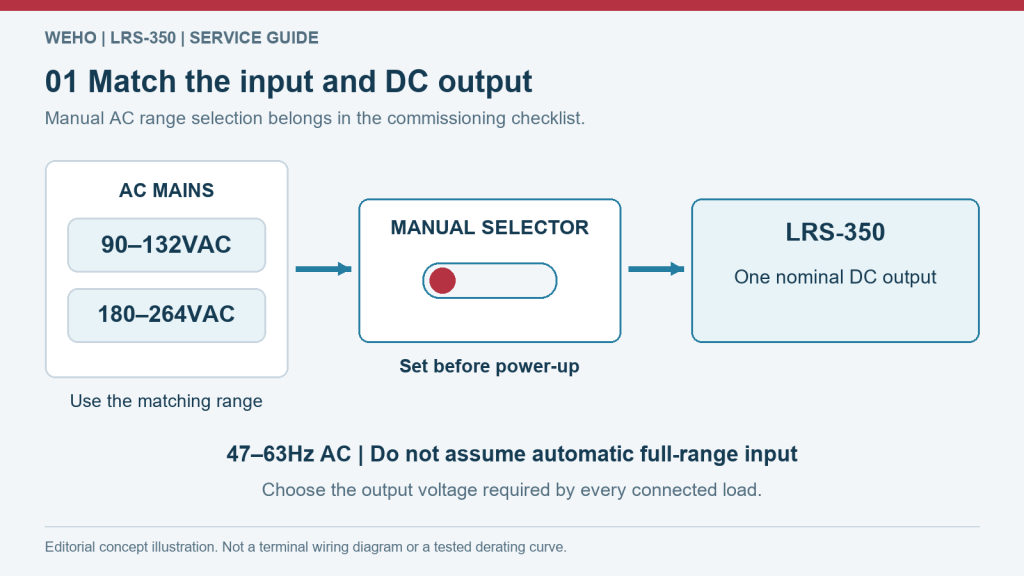
Input and load matching for LRS-400
The sheet specifies 90–132 VAC or 180–264 VAC by switch, 47–63 Hz, and a separate 240–370 VDC input range. Match the AC selector to the actual incoming band while power is isolated; automatic range switching is not stated. Match the selected DC version to every connected input, then include simultaneous demand and startup transients before energising the equipment. The planning image is a representative LRS-series example, not an exact-model wiring diagram.
LRS-350 manual-selector planning example; use LRS-400 input bands, selection instructions and output options, not the example labels.
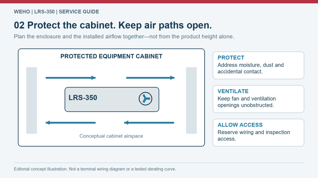
LRS-400 enclosure and service-space planning
Dimensions are 215 × 115 × 30 mm, unit weight is 0.76 kg, and the packing entry is 37.5 × 25 × 26 cm / 20 pcs / 16 kg. Use the model-matched mechanical drawing's mounting and screw-depth references when designing the host support. Reserve additional space for terminal access, conductor routing and the host equipment's airflow; the case outline is not a clearance allowance.
LRS-series cabinet-space concept; the exact case, cooling method and mounting are defined by this model's own technical data.
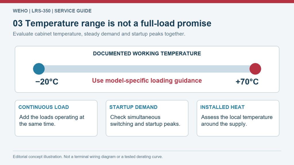
Temperature and duty-cycle assessment for LRS-400
The working-temperature entry is −20°C to +70°C. It provides no load/temperature derating curve and no full-load-at-70°C condition. Measure the temperature at the installed supply and review the longest expected duty cycle. Keep vents unobstructed; do not substitute room temperature for the operating temperature inside the equipment.
LRS-350 temperature-planning example, not a measured derating curve or a replacement for LRS-400 operating limits.
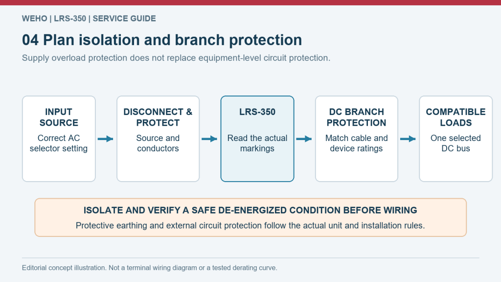
LRS-400 fault recovery and protected installation
The overload entry states 110–150% output cut-off with automatic recovery. Under “Over voltage protection”, the sheet prints “115%~140% rated output power” and describes hiccups mode with automatic recovery after the fault condition is removed. Have a qualified installer check terminal identification, protective earthing and branch protection for the actual assembly. Coordinate restart behaviour with the equipment controls rather than treating supply recovery as a safety function.
Functional power-planning illustration only; follow the exact model's terminal identification and qualified installation instructions.
Application Industries
AI LRS-series planning and application illustrations; equipment scenes are not customer-installation records or exact-model dimensional or wiring evidence.

Retail sign-control and LED-module branches
For the storefront scene, assess an LRS-400 version for the actual compatible module and control groups in a ventilated internal compartment. Check the complete DC distribution and thermal duty, not the family wattage alone. No direct bare-LED, dimming or outdoor-exposure capability is assumed.
Conditional output example: LRS-400-24 (24 V); listed current entry: 0–16.5 A.
AI application concept — retail signage, not an installation record for this product.
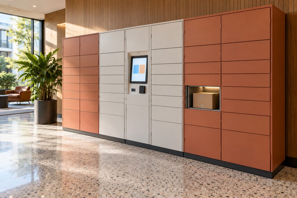
Parcel-terminal interface electronics
A parcel terminal can separate its logic supply from distributed door-release interfaces. Evaluate LRS-400 only against the specified compatible branch loads, including the permitted simultaneous release pattern. Do not infer compatibility with every lock, display or backup system.
Conditional output example: LRS-400-24.
AI application concept — parcel-terminal electronics, not an installation record for this product.
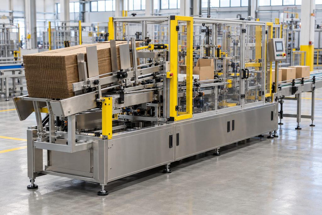
Carton-packaging auxiliary electronics
A carton machine may allocate LRS-400 to a matched group of sensor and controller interfaces after checking the load schedule and recovery behaviour. Provide appropriate branch protection and suppression. Motors, forming mechanisms, heaters and safety functions remain independently powered and assessed.
Conditional output example: LRS-400-24.
AI application concept — carton-packaging auxiliary electronics, not a complete-machine power claim.
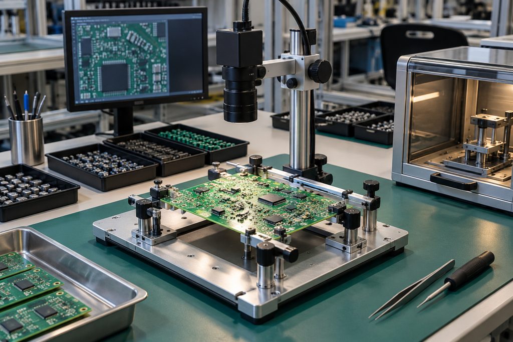
Electronics-fixture auxiliary interfaces
For an electronics inspection station, evaluate LRS-400 for voltage-compatible auxiliary interfaces and qualified converter inputs. Check load-side noise and transients with the actual fixture. The supply is not the measurement instrument, a programmable laboratory output or proof of inspection accuracy.
Conditional output example: LRS-400-12 (12 V); listed current entry: 0–33 A.
AI application concept — electronics-fixture interfaces; no measurement-performance or installed-model claim.
Frequently Asked Questions
Which output choices are listed for LRS-400?
The four entries are LRS-400-12: 12 V, 0–33 A; LRS-400-15: 15 V, 0–26.6 A; LRS-400-24: 24 V, 0–16.5 A; and LRS-400-48: 48 V, 0–8.3 A. Each suffix identifies an alternative single-output model, not another rail on the same supply.
How are the AC input bands and DC input range defined?
The sheet specifies 90–132 VAC or 180–264 VAC by switch, 47–63 Hz, and a separate 240–370 VDC input range. Match the AC selector to the actual incoming band while power is isolated; automatic range switching is not stated. A DC-specific selector procedure is not supplied on this page and needs confirmation for a DC-fed build.
How should the 400 W summary be used in output selection?
The summary prints “Single output: power 400W”. 400 W is the series summary, not a separate continuous rating for every output model. Use the selected suffix's voltage and current entries and establish the operating conditions; do not turn the family description or a voltage-times-current calculation into a replacement continuous rating.
What output adjustment is documented?
The source lists ±10% DC voltage adjustment in all four columns. Check the complete accepted input window of every load before setting an adjusted voltage. No additional current or continuous-power allowance for adjustment is specified.
Which stability and ripple figures belong to LRS-400?
Inlet wire stability and load stability are both ±0.5% across the four outputs. Wave and noise are listed as 150 mVp-p for 12 V, 15 V and 24 V, and 200 mVp-p for 48 V. Measurement bandwidth, probing method and load/ambient conditions are not stated on the page. Those figures alone do not guarantee camera, weighing or process-measurement accuracy.
What efficiencies are printed for the voltage variants?
The sheet lists 85% for LRS-400-12, 86% for LRS-400-15, 88% for LRS-400-24 and 89% for LRS-400-48. It supplies no efficiency curve or explicit test conditions for those percentages. Assess heat and input demand at the intended operating point rather than borrowing a curve from another model.
What protection wording is printed, including the over-voltage entry?
The overload entry states 110–150% output cut-off with automatic recovery. Under “Over voltage protection”, the sheet prints “115%~140% rated output power” and describes hiccups mode with automatic recovery after the fault condition is removed. The heading and power-based wording do not establish a usable voltage threshold, so the threshold basis needs clarification before designing a protection coordination scheme. Do not substitute a percentage of output voltage or an inferred value in volts.
Does the temperature range permit full load at +70°C?
The working-temperature entry is −20°C to +70°C. It provides no load/temperature derating curve and no full-load-at-70°C condition. Verify mounting, ventilation and the actual supply-compartment temperature at the intended load and longest operating cycle.
What timing values and load conditions are available?
The row headed Setup, rise, hold up time gives “1500ms, 50ms/230VAC 1500ms, 50ms/115VAC”. The sheet does not identify a separate hold-up duration or a full-load timing condition. An uninterrupted inspection cycle or ride-through duration therefore needs separate system-level evaluation.
What mechanical and shipping entries are given?
Dimensions are 215 × 115 × 30 mm, unit weight is 0.76 kg, and the packing entry is 37.5 × 25 × 26 cm / 20 pcs / 16 kg. Use the model-matched mechanical drawing's mounting and screw-depth references when designing the host support. A case outline does not specify cable space, electrical clearance or thermal clearance for an installation.
What isolation and connection information accompanies the model?
Withstand values are I/P–O/P 1.5 kV, I/P–FG 1.5 kV and O/P–FG 0.5 kV, for one minute. The isolation-resistance entry is 100 MΩ / 500 VDC / 25°C / 70% RH for the listed I/P–O/P, I/P–FG and O/P–FG paths. The terminal drawing assigns pins 1 and 2 to AC input, 3 to GND, 4–6 to −V and 7–9 to +V. These printed values do not certify the completed host equipment or authorise an improvised wiring arrangement.
Which integration functions remain outside the documented scope?
The sheet does not establish bare-LED current regulation, dimming, battery charging, UPS operation, an ingress-protection rating or a motor-drive rating. For compatible electronics, verify DC input windows, total running demand, startup transients and fault recovery at the selected output. Use separately assessed drivers, converters, protection and host enclosures where those functions are required.
RELATED PRODUCTS


What’s the best Power Supply products for your business?
Boost your business with WEHO quality power supply prooducts.
Ask an Expert